


Deconstruction of a 300 MHz Cryomagnet for NMR Spectroscopy
Abstract
A decommissioned 300 MHz (7 T) superconducting cryomagnet was deconstructed and the insulation necessary to house the superconducting magnet at 4 K was progressively removed. The liquid nitrogen and liquid helium vessels were removed separately. The magnetic core was then dismantled
Keywords: NMR, Superconductors

LIST OF FIGURES


Cylinder Disassembly
Stepwise Decontruction
 circular piece of stainless steel. The magnet was tipped on its side to remove the plate. Tilting the NMR magnet is this way damages the spacers between vessels and makes the magnet inoperable. The magnet was then positioned upright and attached to a block and tackle. The top ends of the liquid nitrogen fill tubes were cut off before the 'Vacuum Chamber' could be removed.")
Figure 1. Left; The base of the ‘Vacuum Chamber’ is removed. Middle; The outside is fastened with a block and tackle. Right; The tubes coming out of the top of the cylinder lead inside to the ‘Liquid Nitrogen Vessel’ and ‘Liquid Helium Vessel’. The filling tube for the ‘Liquid Nitrogen Vessel’ slides through a tube in the ‘Vacuum Chamber’ and is braised at the top.

3. The ‘Vacuum Chamber’ was raised and removed. At least 50 layers of insulating (aluminium coated) Mylar sheet are wrapped around the remaining vessels.

Figure 4. Left; The doughnut shaped ‘Liquid Nitrogen Vessel’ (left) is separated from the ’20 K Radiation Shield’ (middle) that covers the ‘Liquid Helium Vessel’ (right). Right; One layer of aluminium foil is removed to expose the stainless steel ‘Liquid Helium Vessel’.
Figure 5. Left; The base of the ‘Liquid Helium Vessel’ is cut open with an angle grinder and the base with connected copper pipe is removed.
Figure 3. Left; The Mylar sheet was removed. Middle; The top plate is unscrewed from the ‘Liquid Nitrogen Vessel’. Right; The filling tubes to the ‘Liquid Helium Vessel’ are thin stainless tube and break easily.

7. The ‘Liquid Helium Vessel’ is a 3 mm thick stainless steel cylinder that houses the magnet. It was cut open at the base using an angle grinder.
5. The ‘Liquid Nitrogen Vessel’ was removed first (outermost).
Manufactured by Spectrospin and Oxford Instruments. BZH 300/52
Field: 7.05 T Current: 38.6 A
Field: 7.05 T Current: 38.6 A
1. The bottom base plate is unscrewed and the stainless steel ‘Vacuum Chamber’ (outside layer) was secured using a block and tackle.
2. The outside ‘Vacuum Chamber’ shell is braised to the ‘Liquid Nitrogen Vessel’ (inside) via the fill tubes at the top. The top of each tube was cut using an angle grinder.
4. The many layers of Mylar sheet were unwrapped and the top aluminium covering removed. Underneath, the doughnut shaped aluminium ‘Liquid Nitrogen Vessel’ surrounds the inner cylinders and vessels. The two tubes in the middle lead to the central ‘Liquid Helium Vessel’
6. The aluminium ‘20 K Radiation Shield’ was removed (middle) from the ‘Liquid Helium Vessel’ (inner) that is wrapped in a layer of aluminium foil.
8. A copper pipe is welded to the base and slides out of the centre. It fits through the magnet and guides the sample from the top, through the centre of the vessels and into the middle of the magnet.
9. The magnet is attached to a fibreglass base that is screwed to the ‘Liquid Helium Vessel’. Attached to the top is an aluminium heat sink with 6 resistors that are designed to operate at 4K. The screw ends of the steel rods can be accessed when the magnet is filled with cryogens. These are connected to the electronics and coils used to power up the magnet.
10. The magnet was removed from the ‘Liquid Helium Vessel’ and the heat sink was unscrewed.
11. The base (fibreglass) that is used to attach the magnet to the ‘Liquid Helium Vessel’ also holds the wiring and components for the ‘power up ‘and ‘Shim’ coils. It was unscrewed from the ‘Rare Earth Metal Core’ and removed.
Figure 6 The fibreglass base was unscrewed and detached from the ‘Rare Earth Metal Core’

Figure 7. Left; The ‘Shim Stack’ is removed from the centre of the ‘Rare Earth Metal Core’. Middle; The fibreglass tape is removed from around the ‘Shim Stack’ to show the copper ‘Shim Coils’. Right; The ‘Superconducting Wire’ was de-soldered at the bottom and unwound.
12. The ‘Shim Stack’ is removed from the centre of the ‘Rare Earth Metal Core’. The fibreglass tape was unwound to show the copper ‘Shim Coils’.
13. One perfectly wound layer of ‘Superconducting Wire’ was de-soldered (at the bottom) then unwound. Under the first layer of ‘Superconducting Wire’ there is a thin sheet of copper foil, followed by another perfectly wound layer of ‘Superconducting Wire’, joined using a solder join at the top.


Frequently asked questions about plan orders, blade design, electrical work and generator matching can be found on our Q&A pages.


SPONSORED ADVERTISEMENT


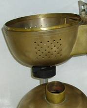
Figure 2. The ‘Vacuum Chamber’ is raised and removed.

FREE
Sample chord sections can be generated for blades between
0.70 to 0.80 m (550 Watts to 710 Watts).
Sample chord sections can be generated for blades between
0.70 to 0.80 m (550 Watts to 710 Watts).

Free Wind turbine Plans for 500W blades included with each purchase


Right; Screwed to the top of the magnet is an aluminium heat sink with resistors rated at 4 K. The electronics for powering up the electromagnet magnet are temporarily connected using the steel rods that can be accessed through the fill ports.


SPONSORED ADVERTISEMENT


14. Under the second layer of ‘Superconducting Wire’ there is a single layer of cardboard that separates three copper ‘Shim’ windings that wrap around the outside of the ‘Rare Earth Metal Core’.
15. A plastic (bakelite) cylinder is fastened with wax over the top of the ‘Rare Earth Metal Core’. The dissection stops at this point. After melting the wax and pouring over 400 mL from the junction between plastic cylinder and the core, it still will not slide off… have to try again another day

Figure 8. Left; After the first layer of ‘Superconducting Wire’ was removed it was de-soldered at the top. Underneath is a thin layer of copper foil that was removed. Middle; Underneath the copper foil is a second layer of ‘Superconducting Wire’ that was also unwound. Right; Under the second layer of ‘Superconducting Wire’ is a cardboard section that contains 3 copper coils (of varying size) wound around the ‘Rare Earth Metal Core’.
The described magnet deconstruction can be compared with the vertical cross-section of a similar (but not identical) NMR magnet documented by JEOL USA.
Dissection of the inner workings of the probe is detailed nicely at the MIT Department of Chemistry, Instrumentation Facility website.
| Figure | Page | |
| 1 | ‘Vacuum Chamber’ preparation | 2 |
| 2 | ‘Vacuum Chamber’ removal | 2 |
| 3 | Mylar removal | 3 |
| 4 | Separating ‘Liquid Nitrogen’, ‘20 K Radiation Shield’ and ‘Liquid Helium Vessel’ | 3 |
| 5 | ‘Liquid Helium Vessel’ dissection and removing the magnet. | 4 |
| 6 | Removing the base | 5 |
| 7 | ‘Shim Stack’ removal and unwinding the ‘Superconducting Wire’ | 6 |
| 8 | Removing the copper foil and the second layer of 'Superconducting Wire' | 7 |


Design custom blades for your generator and calculate power output at each wind speed.


Free sample chord sections can be generated for 0.70 m to 0.80 m blades (550 Watts - 710 Watts).


Free plans for 500 W blades with each purchase.


Chemistry Articles
Design custom blades for your generator and calculate power output at each wind speed.
Free plans for 500 W
blades with each purchase
blades with each purchase

Chemistry Articles

, 5 Metre Diameter Carbon Fibre Blades")


 Measurement Over RF Frequencies Between 0.1 - 40.0 GHz for Common Organic Chemicals.")


1.4 Metre Diameter 3-Blade Wind Turbine Construction

