


Free sample chord sections available

2. Calculating generator efficiency
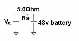
Given: The 3 phases are isolated and connected as 3 single phase outputs. Each output is rectified to DC using a single phase bridge rectifier.
At 666 rpm, generator voltage Vs = 65 Volts.
Voltage across Rs = 65 - 48
Vs = 17 Volts
Vs = 17 Volts
Ploss = V2/R
Power Lost = 172/5.6
Ploss= 51.6 watts per phase
Ploss= 51.6 watts per phase
Efficiency of generator = 144/(144+51.6)
Efficiency = 73.6%
Efficiency = 73.6%
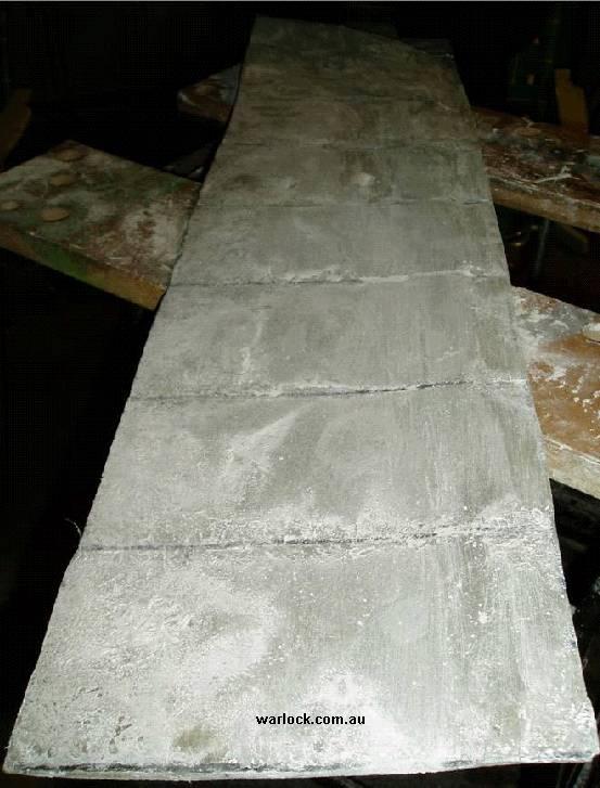
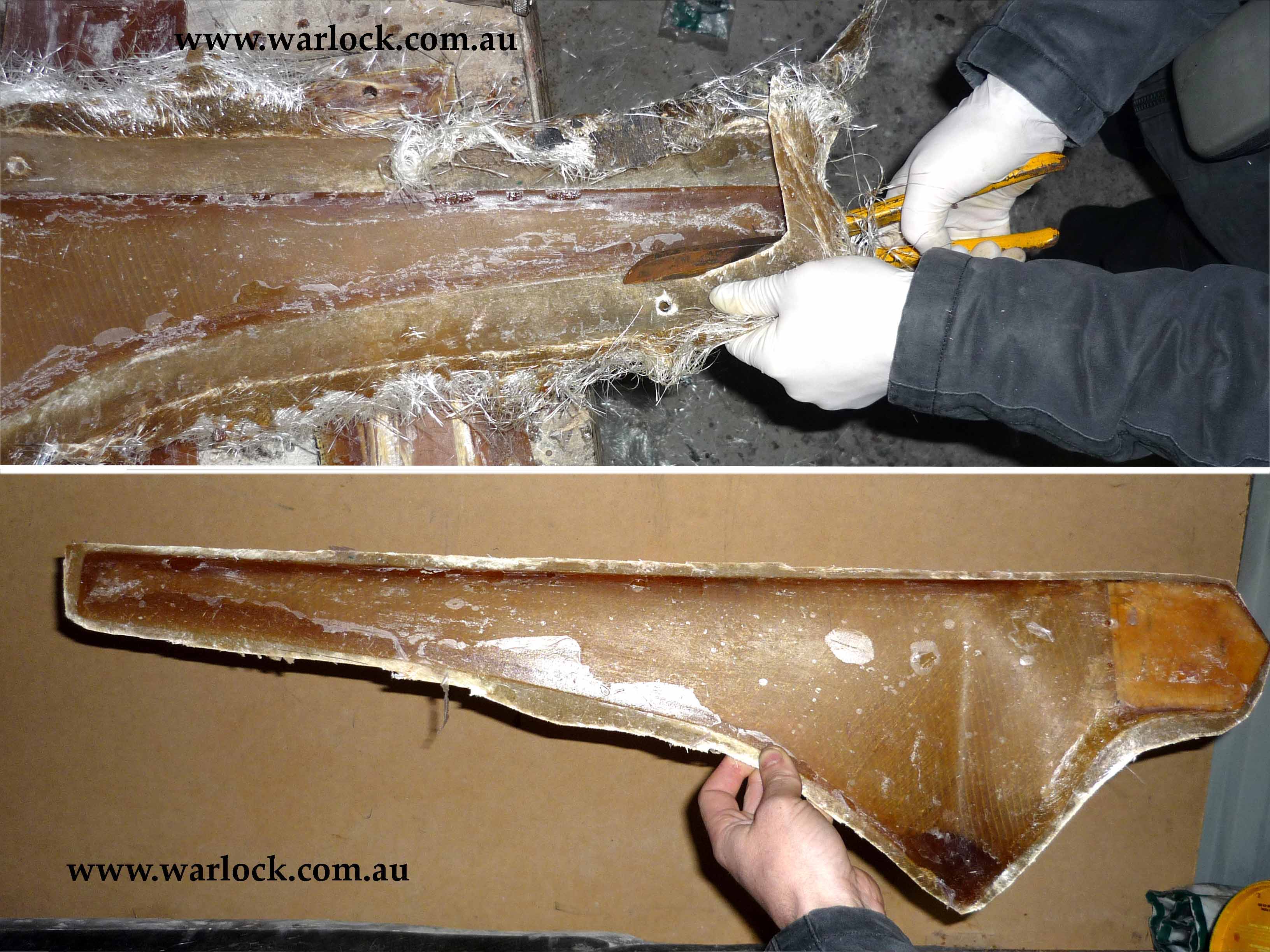
The airfoil cross sections were cut out of 3 mm aluminium sheets. These sheets were bolted to a steel frame, spaced at appropriate distances and aligned.
The gaps between the airfoil sections were filled with aluminium tape and the back of the tape was fibre glassed in place. Wax and mould release was applied to it and two positive moulds were made.
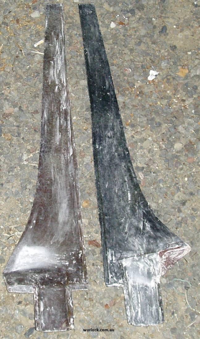
The moulds were sanded down using the aluminium impressions as a guide. Wax and mould release was applied to the positive moulds (in Figure 8) and new negative moulds were made out of fibreglass and carbon fibre (Figure 9).
Careful detailing of the positive mould produced a perfect negative mould. This final negative mould was waxed and mould release was applied. CSM fibreglass (220 g) with vinyl ester resin was applied to each mould. The two mould halves were clamped together after the resin had gelled and the blade was removed after curing.
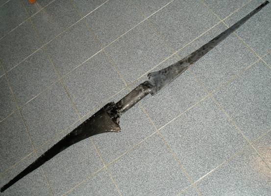
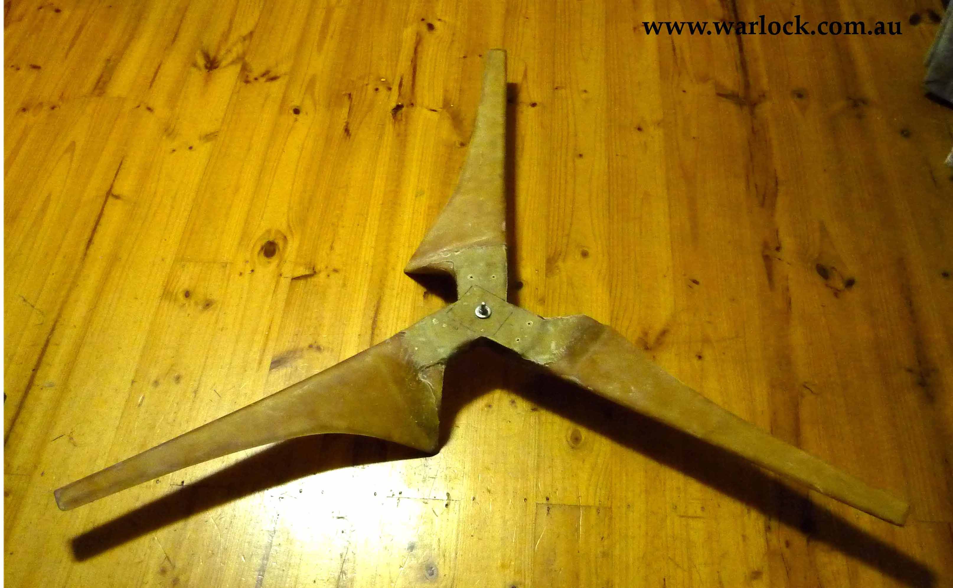
The blades were sanded and wrapped in carbon fibre, using an additional carbon fibre layer around the hub section. The finished blades are extremely light weight.
4. Testing the wind turbine
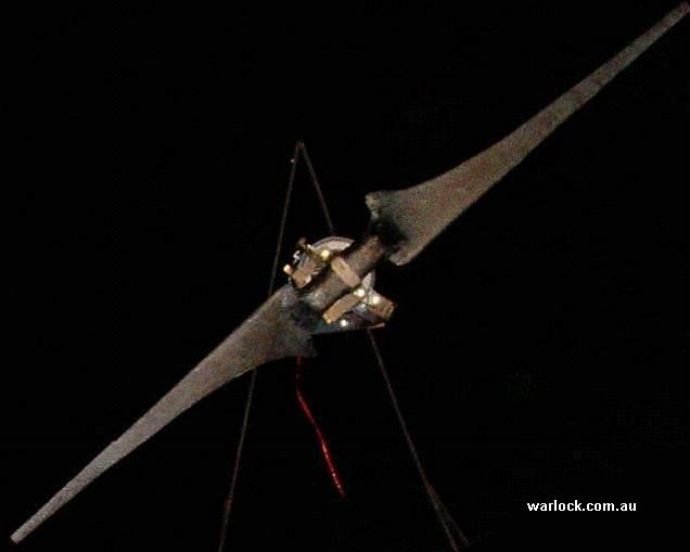
The wind turbine was bolted to a trailer and the rpm, voltage and tsr was measured by connecting the generator to a very high power multi-tap resistor. The turbine was allowed to speed up to an open circuit voltage of 65 V (666 rpm) before the resistor load was connected.
Measurement of results from the wind turbine
Note: Our method of turbine testing generated turbulent wind, affecting
efficiency. The results should be used as a guide only
efficiency. The results should be used as a guide only
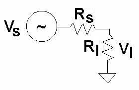
Rs is the resistance of the generator windings plus the power cable; 5.75 ohms
Rl is the resistance of the load; 6.6, 10, 15, 21.5 and 25 ohms
Power generated by the blades was calculated by dividing measured power by the efficiency of the generator.
Once the blades have been characterized
a new generator will be designed.
a new generator will be designed.
Power generated by the blades is calculated using the following method:
Voltage across the resistor load was measured (Vl),
Vs = Vl x [(Rs + Rl) / Rl ]
Power produced by blades and lost in the generator, power cable and resistor load is given by;
P = V2/R
P = Vs2 / (Rs+Rl)
Rotational speed (rpm)
Power (watts)
Blade efficiency
Tip speed (km/h)
Tip speed ratio


Frequently asked questions about plan orders, blade design, electrical work and generator matching can be found on our Q&A pages.

Enable Ads for www.warlock.com.au
SPONSORED ADVERTISEMENT

1 kW Wind Turbine (12.5 m/s)
2-Blades (Carbon fibre), 1.8 Metre Diameter
& Induction motor to PMA conversion
2-Blades (Carbon fibre), 1.8 Metre Diameter
& Induction motor to PMA conversion
Abstract
A 1 kW @ 12.5 m/s (2 kW @ 17 m/s), 1.8 metre diameter wind turbine was designed and constructed using carbon fibre composites. The generator was built by converting an induction motor into a permanent magnet generator. Blade power and efficiency have been measured at different tip-speed-ratios and a maximum efficiency of 30% at a TSR of 11.6 was recorded. These results verify the accuracy of calculations from the blade calculator software. Total cost of the generator and blades was less than AU$200.
Keywords: Wind power, Permanent Magnet Generator, Induction motor to PMA conversion, 1kw wind turbine, carbon fibre wind turbine blades


| Figure | Page | |
| 1 | 40 Amp car alternator rotor with magnets attached | 2 |
| 2 | 40 Amp car alternator rotor with magnets fibre glassed in place | 2 |
| 3 | 40 Amp car alternator stator with shielding | 3 |
| 4 | Completed conversion of the 40 Amp car alternator | 3 |
| 5 | Completed conversion a 1/4 hp induction motor | 3 |
| 6 | Wind turbine airfoil cross-sections | 5 |
| 7 | Turbine airfoil cross-sections bolted to frame | 5 |
| 8 | Positive moulds of wind turbine blades | 6 |
| 9 | Negative moulds of wind turbine blades | 6 |
| 10 | 1.8 m blade set | 7 |
| 11 | Turbine testing | 7 |
| 12 | Measured TSR vs efficiency | 9 |
| 13 | Measured Power | 10 |

LIST OF FIGURES


SPONSORED ADVERTISEMENT


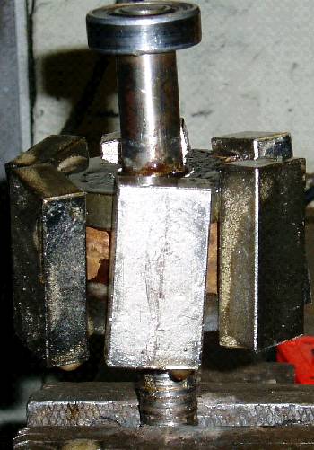
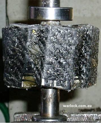
The alternators rotor was turned down on a lathe to accommodate
neodymium magnets.
neodymium magnets.
Design of a permanent magnet generator was necessary to test and
characterise the blade set. Conversion of a 40 amp car alternator to a
permanent magnet generator was attempted.
characterise the blade set. Conversion of a 40 amp car alternator to a
permanent magnet generator was attempted.

1. Construction of the Permanent Magnet Generator
Figure 2. 40 Amp car alternator rotor with magnets fibre glassed in place
Figure 1. 40 Amp car alternator rotor with magnets attached


- Six magnets were carefully placed on a slight angle to reduce cogging of the generator.
- The magnets were fibre glassed in place with two strips of carbon fibre.
Sheet metal was placed inside the stator to shield the magnetic field from aluminium.
Without the sheet metal lining, significant power was lost in the aluminium.
Without the sheet metal lining, significant power was lost in the aluminium.
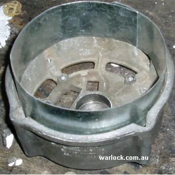
Figure 3. 40 Amp car alternator stator with shielding

Figure 4. Completed conversion of the 40 Amp car alternator
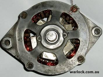
Power output was measured to be less than 500 watts at the rpm of the designed blades. The generator will not produce enough power for the 1.8m diameter blades, it is more suited to 1.0m diameter blades with a high tip-speed-ratio.

Figure 5. Completed conversion of a 1/4 hp induction motor
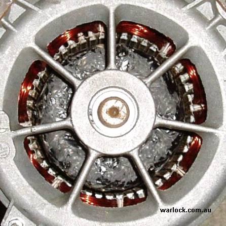
Power output was measured to be more than 2000 watts at the rotational speed for the designed blades. This generator produces enough power for the 1.8 m diameter blades.


V = IR rearranged to;
V/R = I
V/R = I
Current into battery = 17/5.6
I = 3 amps per phase
I = 3 amps per phase
Calculate power using; P = VI

The wind turbine blades were designed using the warlock engineering blade calculator program. The airfoil chosen was NACA2412 and a two bladed turbine was designed to have a tip-speed-ratio of 10.
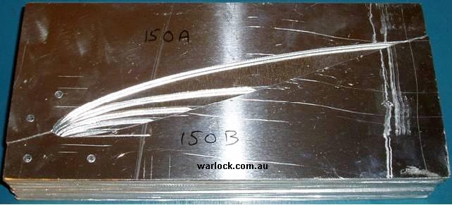


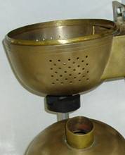
Figure 6. Wind turbine airfoil cross-sections

SPONSORED ADVERTISEMENT
Figure 7. Wind turbine airfoil cross-sections bolted to a frame
Figure 8. Positive moulds of wind turbine blades

Figure 9. Negative moulds of wind turbine blades
Figure 10. 1.8 m blade set
Rs = resistance of each phase of the generator

Power into battery = 48 x 3
P = 144 watts per phase
P = 144 watts per phase
(432 watts for all 3 phases)
3. Design and construction of the wind turbine blades
Figure 11. Turbine testing
Results from the turbine test are tabulated below.


Figure 12. Efficiency vs TSR
Figure 13. Measured Power. Power (Watts) vs Speed (m/s)

Conclusion
The carbon fibre blades maintained a peak efficiency of 27% for all TSR values between 10:1 and 14:1. The maximum power generated was 2.0 kW at 60 km/h wind speed.


Total cost $181
Two Blades $14
Moulds $72
Magnets $80
Induction motor $15
System cost (AUD)

6. Total cost of the
wind turbine
wind turbine
The same technique was used to convert a larger 1/4 hp induction motor into a 8 pole / 3 phase PMG.
Power output was measured to be less than 500 watts at the rpm of the designed blades. The generator will not produce enough power for the 1.8 m diameter blades, it is more suited to 1.0 m diameter blades with a high tip-speed-ratio.
| 25 ohm | 21.5 ohm | 15 ohm | 10 ohm | 6 ohm | |
| 30 km/h | 208 | 205 | 300 | ||
| 40 km/h | 524 | 649 | 332 | 252 | |
| 50 km/h | 950 | 981 | 1017 | 1008 | 940 |
| 60 km/h | 1953 | 2019 | 1873 | 1990 |
The generator has zero cogging, this is due to the angled magnets and the 2 mm air gap between the rotor and stator. It is configured for 3 phase, each phase measuring 5.6 ohms. Output voltage is 130 Vrms at 1333 rpm, increasing linearly with rpm.
Free sample chord sections can be generated for 0.70 m to 0.80 m blades (550 Watts - 710 Watts).
Design custom blades for your generator and calculate power output at each wind speed.
Free plans for 500 W
blades with each purchase
blades with each purchase


| 25 ohm | 21.5 ohm | 15 ohm | 10 ohm | 6 ohm | |
| 30 km/h | 820 | 766 | 809 | ||
| 40 km/h | 1302 | 1363 | 851 | 645 | |
| 50 km/h | 1753 | 1676 | 1489 | 1291 | 1105 |
| 60 km/h | 2365 | 2098 | 1744 | 1607 |
| 25 ohm | 21.5 ohm | 15 ohm | 10 ohm | 6 ohm | |
| 30 km/h | 0.23 | 0.23 | stalled | ||
| 40 km/h | 0.24 | 0.30 | 0.15 | stalled | |
| 50 km/h | 0.22 | 0.23 | 0.24 | 0.24 | stalled |
| 60 km/h | 0.27 | 0.27 | 0.25 | 0.27 |
| 25 ohm | 21.5 ohm | 15 ohm | 10 ohm | 6 ohm | |
| 30 km/h | 278 | 260 | 275 | ||
| 40 km/h | 441 | 463 | 289 | 218 | |
| 50 km/h | 595 | 569 | 506 | 438 | 375 |
| 60 km/h | 803 | 712 | 592 | 546 |
| 25 ohm | 21.5 ohm | 15 ohm | 10 ohm | 6 ohm | |
| 30 km/h | 9.2 | 8.7 | 9.2 | ||
| 40 km/h | 11.0 | 11.6 | 7.2 | 5.5 | |
| 50 km/h | 11.9 | 11.4 | 10.1 | 8.8 | 7.5 |
| 60 km/h | 16.1 | 14.2 | 11.8 | 10.9 |

Related Articles
By comparison, the typical TSR for wood carved blades is 7:1. Although they are cheaper to produce, wood blades rotate at half the RPM, reducing the generators power output to 25%
Rs = 5.6 Ohms

, 5 Metre Diameter Carbon Fibre Blades")


 Measurement Over RF Frequencies Between 0.1 - 40.0 GHz for Common Organic Chemicals.")


1.4 Metre Diameter 3-Blade Wind Turbine Construction


Welcome to Warlock Engineering's free Web-Applications *** Free Software, Tools & Apps. ***
Temperature
Mass
Volume
Dry Volume
Velocity
Area
Pressure


Welcome to Warlock Engineering's free Web-Applications *** Free Software, Tools & Apps. ***