

Cheap solar panel built in one day
42 Monocrystalline cells @ 1.75W each
42 Monocrystalline cells @ 1.75W each
Abstract
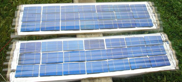
A 42 cell solar panel was constructed in less than a day using low cost materials available from the hardware store. The enclosure was constructed out of plywood and coated in highly reflective mylar. The cells were joined together in series and glued on spacers on top of the mylar. UV resistant polycarbonate sheeting was used to protect the panel and to reflect tangental light onto the cells.
Keywords: Solar cells, Photovoltaic, PV, diy solar panel

| Figure | Page | |
| 1 | Left: The back of the solar cell with copper wires. Right: Top of the cell with six points pre-soldered onto the conductive strip. |
1 |
| 2 | A temperature controlled soldering iron using a variac. | 1 |
| 3 | Top: Top view of the cells soldered together in series. Bottom: Bottom view of the cells soldered in series. |
1 |
| 4 | The cells soldered in series in three rows of seven on top of a wooden base. | 2 |
| 5 | An enclosure constructed using wooden ends to fit the corrugated polycarbonate sheeting over the top of the base. | 2 |
| 6 | Highly reflective mylar sheet was glued to the walls of the enclosure. | 2 |
| 7 | The cells glued to shock absorbing cardboard. | 3 |
| 8 | The polycarbonate sheet screwed to the wood. | 3 |
| 9 | The corrugated dome catching additional tangential light which would normally be lost with a flat panel. | 3 |
| 10 | The cells output is currently undergoing practical testing. | 4 |
| 11 | The cells after 6 months practical testing. | 4 |
| 12 | Cells without polycarb cover. | 5 |
| 13 | Closeup of damaged cells. | 5 |
| 14 | Solar panel with damaged cells bypassed. | 5 |
| 15 | Measured results after 6 months testing | 6 |

LIST OF FIGURES


1. Connecting the solar cells together
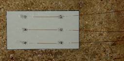
Strands of copper wire were tinned and soldered to the pads on the back of each cell. Six points were pre-soldered on the conductive strip on the top of the solar cell using a low temperature soldering iron. We adjusted the temperature of the soldering iron using a variac.
Figure 1. The back of the solar cell with copper wires (top). Top of the cell with six points pre-soldered onto the conductive strip (bottom)
Figure 2. A temperature controlled soldering iron using a variac
2. Constructing An Enclosure
Cells were connected together in series by soldering the three lengths of copper wire to the top of the next cell.
Wooden ends were cut to fit the corrugated polycarbonate sheeting. The polycarbonate sheeting protects the cells from physical damage and also protects the panel from UV light.
Figure 5. An enclosure constructed using wooden ends to fit the corrugated polycarbonate sheeting over the top of the base
Highly reflective mylar sheet was glued to the surface of the wooden enclosure. This was used to reflect thermal radiation away from the base of the panel.
Figure 6. Highly reflective mylar sheet glued to the walls of the enclosure


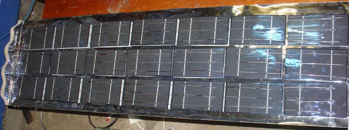
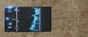
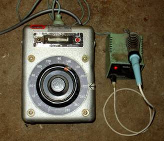
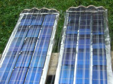
Figure 10. The cells output is currently undergoing practical testing

Figure 9. The corrugated dome catches additional tangential light which would normally be lost with a flat panel


Frequently asked questions about plan orders, blade design, electrical work and generator matching can be found on our Q&A pages.


Free sample chord sections available for blades between 0.70 m and 0.80 m.


SPONSORED ADVERTISEMENT

Design custom blades for your generator and
calculate power output at each wind speed.


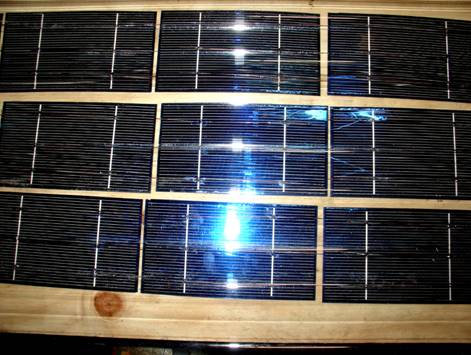
Figure 4. The cells soldered in series in three rows of seven on top of a wooden base

Free Wind turbine Plans for 500W blades included with each purchase.


The cells are extremely fragile and are easily damaged by falling braches.


3. Results: Updated 6/1/2013
Figure 11. The cells after 6 months practical testing

Figure 12. Cells without polycarb cover
17 undamaged cells are wired for final testing.
Figure 13. Closeup of damaged cells
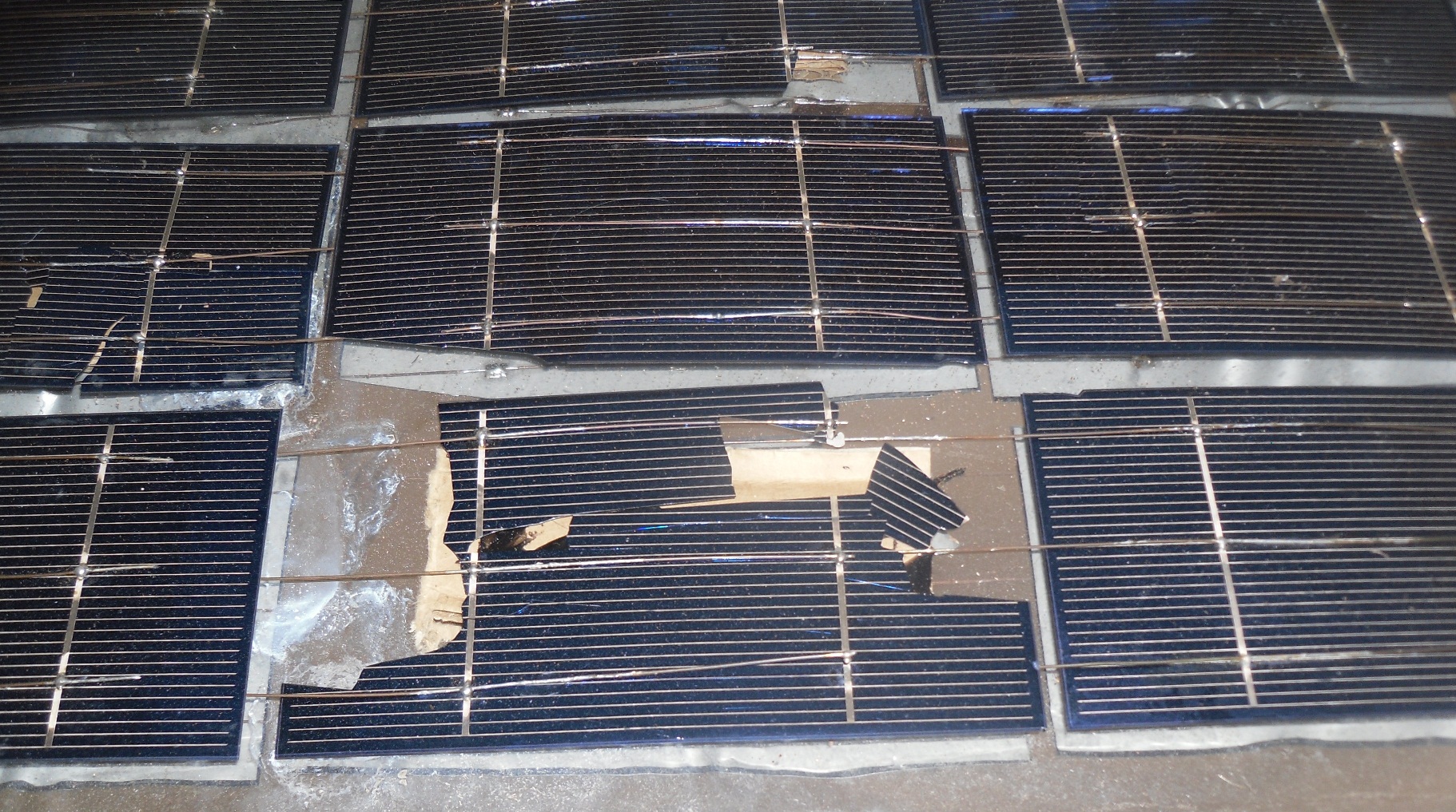

Figure 14. Solar panel with damaged cells bypassed
Ebay Specifications:
Average Values
Power (Watts): 1.75 Wp
Current (Amps): 3.5 Imax
Voltage (Volts): 0.5 Vmax
Average Values
Power (Watts): 1.75 Wp
Current (Amps): 3.5 Imax
Voltage (Volts): 0.5 Vmax
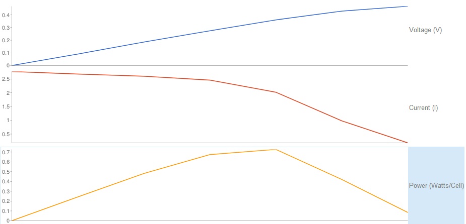
Figure 15. Measured results after 6 months testing

Figure 3. Cells are soldered together in series. Top view (top) and bottom view (bottom) are both shown

Three rows made from seven cells were connected in series to make a panel. (Two panels were constructed).
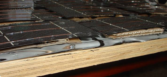
Cardboard shock absorbers were glued between the fragile cells and the mylar sheet to hold them in place and protect them from cracking.
Figure 7. The cells glued to shock absorbing cardboard
The polycarbonate sheet was screwed to the curved plywood ends. Power is connected using brass bolts that protrude through the wood.
Figure 8. The polycarbonate sheet screwed to the wood
Measured Results after 6 Months of Testing
Free sample chord sections can be generated for 0.70 m to 0.80 m blades (550 Watts - 710 Watts).


