


Abstract
A 1.4 metre diameter wind turbine was designed and constructed out of kevlar/glass composite material. The blades have been designed to produce useable power in 30 km/h (8 m/s, 150 W) to 60 km/h (16.6 m/s, 1 kW) wind speeds. This 3-blade turbine was constructed using an inverse camber NACA2412 airfoil. The blade power and efficiency was measured at various tip-speed-ratios. Total cost of the mould and blades was less than AU$300
500 Watt Wind Turbine (12.5 m/s)
3-Blades (Kevlar)
1.4 Metre Diameter
3-Blades (Kevlar)
1.4 Metre Diameter
Keywords: Wind power, Windmill, 3 blade wind turbine, laminar flow, inverse camber

Paper stencils of airfoil shapes were glued onto balsa and cut out using a scalpel. A flat angle-guide was made using sheet metal and is used to set the angle of airfoil sections.
A root made from a round piece of steel rod (2 mm) is glued to the top of the angle-guide and is used to position the rounded end of each airfoil section. The root-guide was fibreglassed and sanded flat.
Construction of the blade skeleton


The blade skeleton was coated in white gelcoat to strengthen it and pieces of clear plastic sheet were glued on the airfoil shapes to create a wing surface. The corners and joins were sealed with aluminium tape.
A border was made out of modelling clay to create a mould for the plaster to be poured into.
A border was made out of modelling clay to create a mould for the plaster to be poured into.


Making a plaster mould
Making a fibreglass blade mould
The plaster mould was waxed then filled with fibreglass to make a fibreglass wing. After curing, the plaster is removed and the wing was sanded smooth. A wooden triangle hub piece was glued in place.
Cardboard and foil was used to make a border, then it was filled with fibreglass and resin to make a fibreglass mould.


The hub for the blade skeleton was made from a piece of wood that was glued onto the root section. The balsa airfoil shapes were positioned and glued along the root.


ADVERTISEMENT

ADVERTISEMENT


Making the blade
The half moulds were filled with pre-cut shapes of fibreglass and kevlar, then the resin was soaked into the glass with a paintbrush. A wooden hub is inserted at the end of the mould.
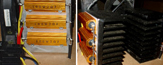
The mould halves were pressed together and tightened using bolts around the border. After the resin cured, the mould was broken apart using a knife and a screwdriver.
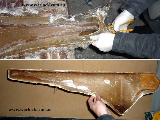
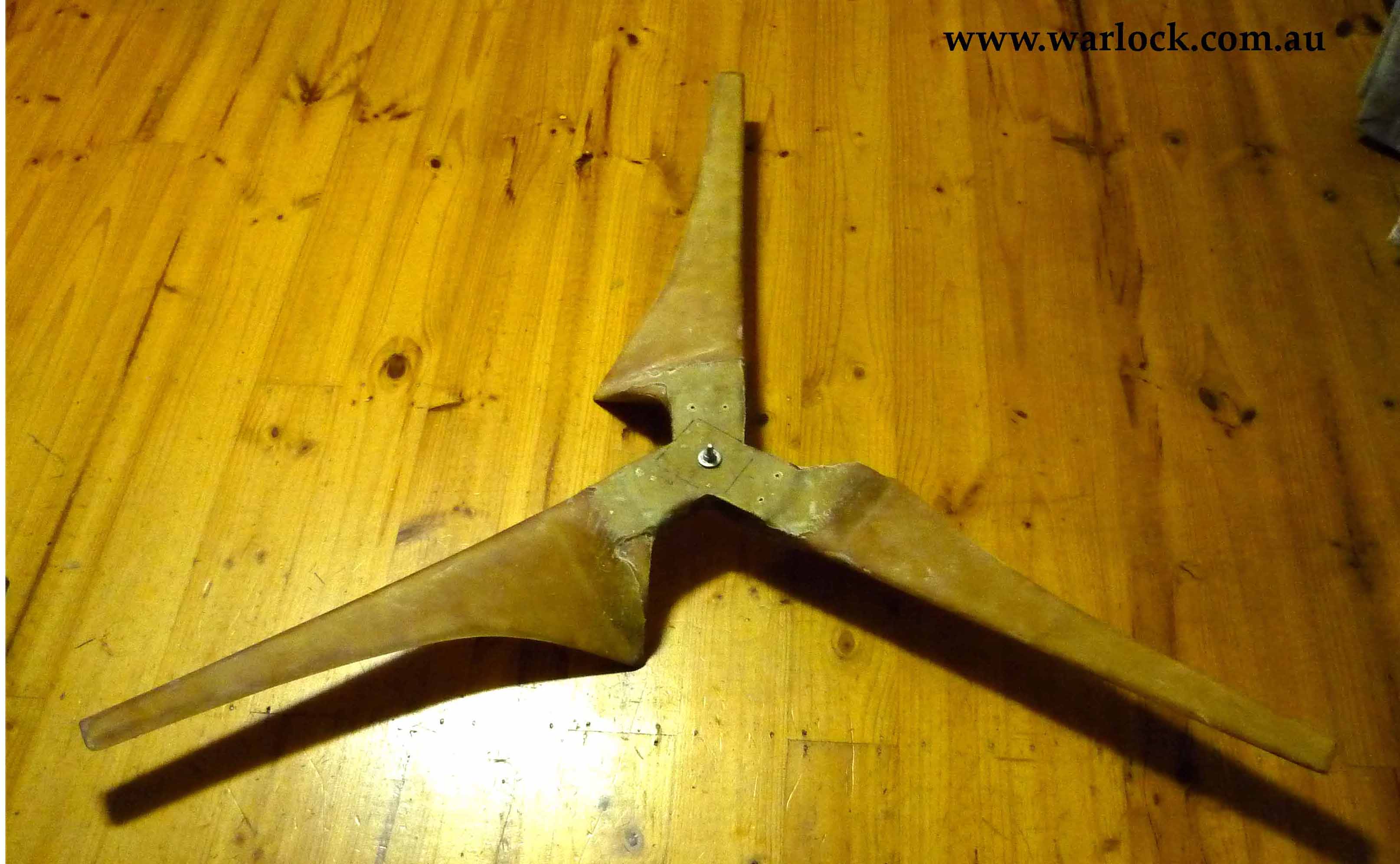
The blade was broken out of the mould and the edges were cleaned up using a pair of snips. After some sanding, each blade was wrapped in a layer of fibreglass cloth. The three blades were fitted together and reinforced using layers of fibreglass.


Continue to summaries about.....

Dumpload Charge Controller


Frequently asked questions about plan orders, blade design, electrical work and generator matching can be found on our Q&A pages.
Plaster and gauze was poured into the mould. After setting, the process was repeated for the other side to complete the mould.
The other side of the mould was fibreglassed and the border was cut square. The mould opened easily and was waxed up before use.
The finished blades were tested using the generator shown in the 1.8 m blade wind turbine. The results are shown below.


Next
Page
Page
Figure 9. Fibreglass blades from the mould (top). The finished 3 blade set (bottom).
Figure 8. A moulded blade ready to be cured (top). Breaking the cured mould apart (bottom).
Figure 7. Half moulds being filled with glass and soaked in resin (top). A wooden hub is fitted at the end (bottom).
Figure 6. Making the fibreglass mould (top) and waxing before use (bottom).
Figure 5. The fibreglass blade from the plaster mould (top). Making the fibreglass mould from the blade (bottom).
Figure 1. The airfoil shapes were constructed using balsa (top). The root and angle-guide were made from tin sheet and wire (bottom).
Figure 2. The root section glued to the hub (top). The balsa airfoil shapes glued along the root (bottom).
Figure 3. The gel coated skeleton with plastic sheet glued to the balsa shapes (top). The final blade skeleton with border made of modelling clay (bottom).
Figure 4. Making the plaster and gauze mould (top). The two completed half moulds (bottom).